Heater Switch Page
![]()
I decided to make a new page with this information on it. Those really interested can read about the problem and others can ignore it.
The first picture shows a section of a wiring diagram for an original harness. At the top of the Picture is the 2-speed switch I have and toward the lower middle right is the 2-speed switch described in the Painless instructions.
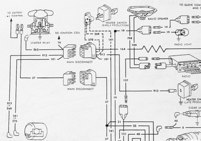
Partial schematic of original wiring harness
The early production switch is shown top center. Wire #181, #268, #270 and #913 are brown, red, orange (blk/ylw?) and yellow, respectively. Note: The blower motor is at the bottom left and should show a black ground wire for early production switch but not for the late production and three speed switch.
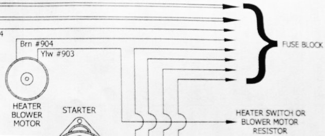
Partial schematic Painless harness
This wiring corresponds to the 2-speed late production switch. Their #903 yellow corresponds to Ford's #913 yellow. The brown wire #904 does not go directly to the fuse block but ends with a blue blade plug under the dash. I have connected it to the orange wire of the blower switch plug using the unused brown wire #900 which is terminated with the correct blade plug.
Note: 1964-1/2 through 1966 Mustangs had three types of Blower Motor Switches, two types of two speed switches and a three speed switch. Early production switches have three wires a red, an orange possibly blk/ylw, and a brown wire. The late production switch is as described below. Decide which type of switch you have and connect the opposite end of wire #903 (ylw) according to the one of the following steps.
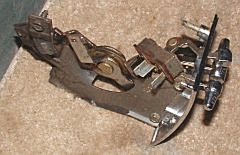
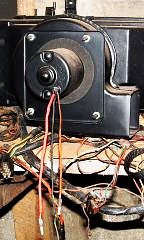
Early production heater blower switch
Car build date is 09/16/1964
It is a single pole double throw center off switch, therefore power is fed to the center terminal and switched between the end terminals.
7.13.0a With the early production 2-speed switch connect the brown wire to the orange wire on the blower motor and the yellow wire to the red wire on the blower motor also be sure to properly ground the black wire of the blower motor.
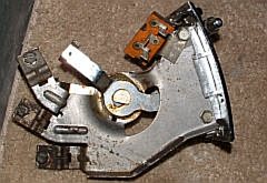
7.13.0b Look at the Painless wire harness under the dash in the area of the heater controls. There should be four blue blade plugs (2M, 2F). Two are connected to a blk/wht wire and a #900 brown wire that can be removed from the harness that includes the Emergency flashers wires. The other two are connected to power (blk/wht) from the fuse block and the #904 brown from the blower motor. The first picture below shows the original switch plug and the blk/wht wire and brown wire removed from the emergency flasher harness. It is best to use the original plug for the switch.
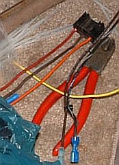
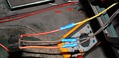
For early production 2-speed switches connect the #904 brown wire that is connected to the orange wire of the blower motor to the orange wire of the blower switch plug using the brown wire #900 that was removed above. Connect the #903 yellow wire that is connected to the red wire of blower motor to red wire of the switch plug as shown in picture on the right above. Connect the blk/wht wire with the blue plug terminal to the brown wire of the center terminal of the switch plug using the blk/wht wire removed above. Then connect the blue blade terminal to the terminal on the blk/wht wire from the fuse block as shown below.
7.13.1 For the late production 2-speed switch connect wire #904 (brn) in ENGINE SECTION B to the (brn) wire on the Heater Blower Motor, this wire supplies power from the fuse block. (This does not match with my harness. The #904 brown wire ends under the dash in a blue blade plug. I assume it is to be connected to the blk/wht power wire from the fuse block in the case of the late production 2-speed and 3-speed switches.
7.13.2 For the late production 2-speed switch connect wire #903 (ylw) in ENGINE SECTION B to the ylw wire on the Heater Blower Motor.
7.13.3 For late production two speed switches connect wire #903 (ylw) to the blower motor switch.
The sections numbered 7.13.0a or b have been added by me. I also made changes in the Note otherwise the material comes from the Painless manual. Illustrations are all mine. I also added the color cues for the wires.

Last update February 28, 2005
Return toMustang Page 2
Return to Armitage's
Home page
Return to Reassembly page
Return to Mustang Page 1